
Laying Out a Multi-Conveyor System: Inclines, Reversing Runs, Accumulation, and the Controls Each Conveyor Needs
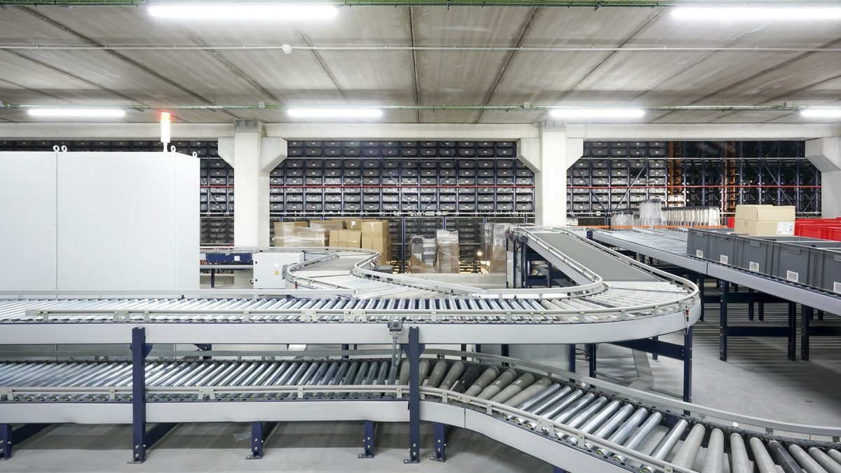
A multi-conveyor line is laid out by settling six things in order: where the product has to climb or descend and at what angle, which runs must reverse, where the line buffers when something downstream stops, how each transfer closes the gap, whether every conveyor gets its own drive, and which conveyors need a sensor at all. Inclines are set by angle and belt: flat belts on Dorner's 2200 low-profile Z-frames run at 5, 10, 15 and 20 degrees and cleated belts at 30, 45 and 60; the 3200 modular Z-frame publishes its own angle set. Reversing runs need a center drive and a reversing gearmotor or VFD, because a reversed end drive becomes a pushed belt and loses roughly two thirds of its capacity. Buffers go ahead of the constraint machine. Each transfer is a choice between an inline gap, a nose bar, a plate, a 90 degree module or a powered transfer. One VFD per conveyor buys independent speed; grouping motors on one drive saves cost and panel space but forces one speed and individual overload protection per motor. Sensors go only where product stops or is counted. The single-conveyor decisions (belt type, frame height, sanitary tier) are covered in our earlier article on specifying a conveyor; this one covers what changes when conveyors are chained.
Inclines: angle first, belt second
Elevation change and available floor length force the angle, and the angle decides the belt. Dorner's 2200 Series Low Profile Z-Frame runs flat belts at 5, 10, 15 and 20 degrees and cleated belts at 30, 45 and 60 degrees, at up to 250 ft/min and loads up to 80 lb (flat) or 50 lb (cleated). The 3200 Series modular Z-frame lists flat belt angles of 5, 10, 15 and 30 degrees and cleated angles of 5, 10, 15, 30, 45 and 60 degrees, with 1 in and 3 in cleats and loads up to 500 lb.
Two consequences follow.
A cleated incline cannot discharge across a nose bar or plate, so the receiving conveyor must accept an inline drop. And Dorner's manuals state for Z-frame models that "belt direction is not reversible," so reversing happens on a different conveyor.
Reversing runs: center drive and a reversing motor
A reversing run is a shuttle between two machines, a reject lane that pulls back, or a buffer feeding either of two outlets. Dorner's manuals say that "since belts are being pulled, positions A and D are preferred," and that "pushing belts (B and C) reduce conveyor load capacity by approximately 66%." Reverse an end-drive belt and the pulled run becomes the pushed run, so the conveyor is derated in one direction. Dorner's bi-directional guidance is a center drive with "only one reversing motor" in the belt return, where sprocket engagement on a modular chain "occurs over 180 degrees of rotation." On the 2200 belted line, center drive also carries the higher rating, 120 lb against 80 lb for end drive.
The gearmotor must be rated for reversing and the controller or VFD wired for forward and reverse. Tracking on Dorner belted conveyors is by V-guided belt, which "virtually eliminates the need for tracking adjustments"; Dorner's published pages do not state a reversing rating for straight belted conveyors, so ask for the exact belt and guide at your load before you commit.
Accumulation: buffer at the constraint
Dorner frames accumulation around one machine: "maximize line uptime by keeping your constraint running." The buffer belongs upstream of it, sized to the longest expected downstream stoppage. Then decide how much contact pressure the product can take while it waits.
For low back pressure the belt does the work: the 3200 modular line lists low backpressure roller top and friction insert belts, including on curves, and Dorner's ERT pallet conveyors use "slip rollers for low backpressure accumulation." For zero back pressure, Dorner describes pressureless loop technology that "protects your products by eliminating backpressure," and accumulation tables for "when in-line accumulation conveyors do not offer enough product accumulation space." Zoned accumulation is the controls version: on the ERT250 "each zone acts independently of other zones," a stopped pallet "will stop in the next zone," and the system "uses pallet sensors and control logic to determine when a pallet is free to move forward, or if a pallet is stopped downstream," with up to four zones and a gearmotor per zone on one conveyor.
Transfers: the gap at every handoff is a decision
Ten conveyors means nine or more transfers, each chosen, not inherited. Dorner's comparison gives the trade: an inline transfer is simplest but leaves a gap of "as little as 1.25 inches" and "is not ideal for very small products"; a nose bar closes it to "as little as 0.31 inches" but is "not recommended for high-speed applications"; transfer plates bridge the gap but need guiding; a 90 degree transfer changes direction but "product orientation is not maintained"; a powered transfer leaves "no gap between conveyors" and "maintains product speed and orientation," but "some modules require added sensors and programming." The 3200 powered transfer handles parts "as small as 3 in in diameter"; the 2200 16 mm nose bar is rated to 200 ft/min and the 8 mm to 75 ft/min. The nose bar and plate options are covered in the single-conveyor article. List the shortest, lightest and least stable product at each transfer, then pick the simplest transfer that handles it at that section's speed.
One VFD per conveyor, or grouped drives
A drive per conveyor gives independent speed, independent stop and start for accumulation, and no single point of failure. Grouping motors on one VFD is permitted "if the right design considerations are made and appropriate protection is provided for each motor," provided "each motor can operate at the same speed and can accommodate a VFD as a single point of failure." The protection requirement changes the panel: "NEC Article 430 Part III requires individual motor overload protection, which is (thermal) overload function, on the load side of a VFD," because "a VFD can only sense its total connected load and cannot sense which individual motor is drawing high current." The payoff is "lower cost, reduction in panel space and reduced control complexity." Pure transport sections that always run together can share a drive; anything that accumulates, indexes, reverses or feeds a machine at its own rate needs its own.
Which conveyors need a sensor
Dorner's photo eye kits describe two base functions: in end-stop mode the "conveyor will run until the photo eye is blocked," and in indexing mode the "conveyor is stopped and will run when the photo eye is blocked." So: a conveyor that discharges into a machine or a stop gets an end sensor at the discharge; an accumulation conveyor gets a sensor per zone; a pure transport section between two running conveyors needs none. Powered transfer modules may bring their own.
Guarding at transfers and inclines
The conveyor safety standard is ASME B20.1-2024, which "applies to the design, construction, installation, maintenance, inspection, and operation of conveyors and conveying systems in relation to hazards." The safeguarding standard is ANSI B11.19-2019 (R2024). OSHA 29 CFR 1910.212(a)(1) requires guarding against "ingoing nip points, rotating parts, flying chips and sparks," and 1910.219(e)(3)(i) requires that "vertical and inclined belts shall be enclosed by a guard." Nip points multiply at every transfer and inclined belts at every Z-frame, so the guarding count is a system number.
What a vendor needs to quote a system
Dorner's RFQ form asks, per conveyor, for belt width, length, drive position, flat or cleated belt with cleat height and spacing, top of belt height from floor, fixed or variable speed and DC or VFD, voltage and phase, maximum load, whether parts accumulate, and how products are "presented to and discharged," with a sketch for curves and Z-frames. Its installation questionnaire adds whether the install interfaces with other equipment, runs through structures, hangs from the ceiling, and any panel or wiring requirements. For a system, combine those into one package:
- Product flow diagram showing every conveyor, direction, and reversing run
- Rate per conveyor in parts or feet per minute, plus the constraint machine's rate
- Elevation at both ends of every conveyor, and the angle of each incline
- Floor plan with columns, doors, drains and existing equipment
- Product list per transfer: smallest, lightest, least stable item
- Accumulation: how much, where, and low or zero back pressure
- Utilities at each drive: voltage, phase, air
- Controls architecture: drive per conveyor or grouped, sensor list, E-stop zones
- Who supplies controls: vendor, integrator, or plant
- Guarding standard and lockout requirements
Sources
- Dorner Conveyors, 2200 Series Low Profile Z-Frame (LPZ) Conveyors
- Dorner Conveyors, 3200 Series Straight Modular Z-Frame
- Dorner Conveyors, 3200 Series Conveyors Engineering Manual (2024)
- Dorner Conveyors, 2200 and 2700 Series Conveyors Engineering Manual (2024)
- Dorner Conveyors, Industrial Accumulation Applications
- Dorner Conveyors, Which Product Transfer is Best: Pros and Cons of 6 Transfer Methods
- Rockwell Automation, Control Multiple Motors with Just 1 VFD
- Rockwell Automation, Controlling Multiple Motors with One VFD
- Dorner Conveyors, Create Zones for Better Control (June 30, 2021)
- Dorner Conveyors, Bi-Directional Plastic Chain Center Drive Conveyor
- Dorner Conveyors, 2200 Series Conveyors V2 product brochure
- Dorner Conveyors, 3200 Series Belted Conveyors
- Dorner Conveyors, 3200 Series Modular Belt Conveyors
- Dorner Conveyors, ERT250 Multiple Zone Conveyor
- Dorner Conveyors, Accumulation
- Dorner Conveyors, Photo Eye Kits and Photo Eye Bracket Kits, manual 851-619 Rev. C
- ASME, B20.1 Safety Standard for Conveyors and Related Equipment (2024 edition)
- ANSI B11 Standards, ANSI B11.19-2019 Performance Requirements for Risk Reduction Measures
- ANSI B11 Standards, ANSI B11.19-2019 (R2024)
- eCFR, 29 CFR 1910.212 General requirements for all machines
- eCFR, 29 CFR 1910.219 Mechanical power-transmission apparatus
- Dorner Conveyors, Conveyor RFQ Form
- Dorner Conveyors, Install Quote Questionnaire
- Stateside Industrial Solutions, Specifying a Conveyor for a Packaging or Assembly Line
All sources retrieved and independently verified October 2026.
Planning a line with more than one conveyor?
Stateside is an authorized Dorner distributor. Send us the flow diagram, the rate at each conveyor and the elevations, and we will return a system layout review before you request a quote.
Request a Quote →