
Specifying a Thermal Mass Flowmeter for Gas Service: Why the Gas, the Line Size, the Flange and the Insertion Length All Change the Part Number
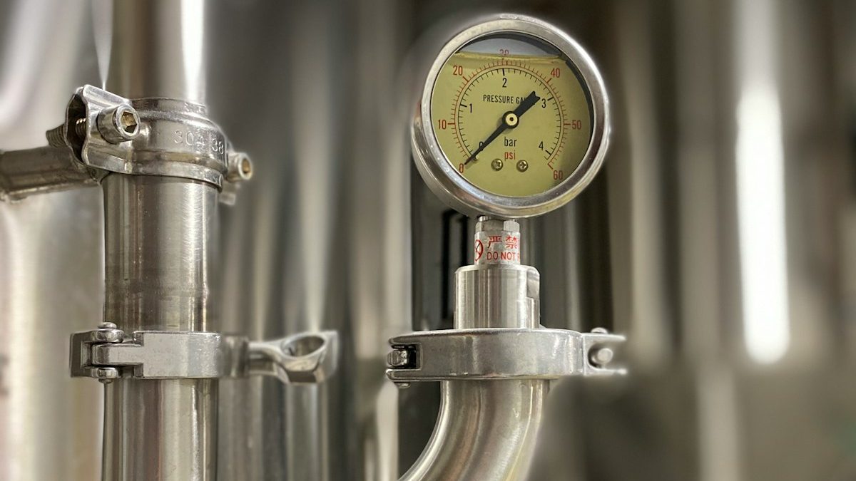
A thermal mass flowmeter infers gas mass flow from how fast the gas carries heat away from a heated sensor, so it is calibrated for a specific gas or mixture; change the gas and the calibration no longer applies, which is why the gas is part of the model code. Line size matters because an insertion probe must reach a defined point in the pipe and an inline body must match the pipe bore. The flange or fitting is a separate code because the connection sets the pressure rating; the same probe is rated differently in a compression fitting, a hot tap or a flange. Insertion length is its own line item because the probe is cut to put the sensor at the correct depth for that pipe and fitting stack-up, and longer approved probes may need an added seal. Add output, power and area classification, and six questions are the minimum.
How a thermal mass meter actually measures
Thermal dispersion meters compare two temperature-sensitive elements in the gas stream. One tracks gas temperature; the other is heated. The flowing gas cools the heated element, and either the power needed to hold a fixed temperature difference (constant temperature differential designs) or the temperature difference at fixed power (constant power designs) is related to mass flow. Fox Thermal's FT4X manual puts it simply: a heated sensor "transfers heat in proportion to the stream's mass velocity." Because the sensor responds to mass, the meter reports mass or standard volumetric flow without separate pressure and temperature compensation.
Two consequences follow. First, heat removal depends on the gas's thermophysical properties: viscosity, density, specific heat, thermal conductivity and thermal expansion coefficient, as Fluid Components International's technical article lays out. Air, nitrogen, carbon dioxide, methane and a digester or flare gas blend each carry heat differently, so the calibration is gas-specific. ASME MFC-21.2 limits the technology to "single-phase pure gases and gas mixtures of known composition," and ISO 14511:2019 likewise covers gases and gas mixtures only. Second, "standard" flow (SCFM, Nm3/h) is only meaningful at a stated reference. Sierra Instruments' QuadraTherm datasheet rates flow at 21.1 °C (70 °F) and 1 atm, with some footnotes at 0 °C. If the old and new meters use different reference conditions, the numbers will not match even with identical hardware.
What happens when the gas changes
Fox Thermal's gas-selection datasheet states that "a change in gas composition on-site triggers a need for a factory recalibration" unless the meter can re-correlate in software. A Sierra product release notes that when field composition drifts from the calibration gas, "the accuracy of the flow meter is adversely affected," and that historically "the only way to correct for a change in gas composition was to return the meter to the factory."
Modern transmitters soften this with gas libraries. Fox's line is calibrated on a single gas at the factory and lets the user select other pure gases or enter a mixture from the display, Modbus or PC software. Sierra offers additional "dial-a-gas" selections plus an optional licensed mixing tool. The accuracy is not the same as an actual-gas calibration, though. On Sierra's datasheet the calibrated gas carries plus or minus 0.5 to 0.75 percent of reading, while selectable gases are typically plus or minus 3.0 percent of full scale and hydrogen 5.0 percent. FCI's technical article draws the same line: equivalency methods approach "2-3% of reading," while "the highest level of performance is made available through actual gas or actual liquid calibrations." For natural gas, Fox warns its preset is only an average and recommends programming the sampled composition. No manufacturer publishes a general error figure for running an air calibration on carbon dioxide; any number you are quoted is that vendor's estimate for that meter, not a property of the technology.
Practical rule: name the gas and, for mixtures, the composition and how much it varies.
Insertion versus inline, and what each needs
An insertion meter is a probe pushed through a fitting into an existing pipe, ordered by probe length. Fox's manual gives an insertion depth formula that adds the fitting height, half the pipe diameter and a fixed offset so the sensor window sits just past the centerline for pipes 2 inches and larger, with a different rule for 1-1/2 inch pipe. Sierra lists probe lengths from 6 to 48 inches, requires a 2 inch minimum pipe, and notes that agency-approved probes longer than 13 inches need an added conduit seal that adds 6.2 inches to the stack-up. Get the pipe outside diameter and schedule, the coupling or weldolet height and any valve or retractor between fitting and pipe wall before picking a length.
An inline meter is a flanged or threaded body with the sensor built into a short pipe section, often with integral flow conditioning, ordered by nominal size and end connection: NPT, Class 150 or 300 flanges, or DN PN16 and PN40 flanges.
Straight run is where the designs diverge most. Fox's FT4X manual, Figure 2.1, asks for 8 pipe diameters upstream and 4 downstream on the inline version, and 15 upstream and 10 downstream on the insertion version. Sierra's table calls for 15D upstream and 1D downstream of a single elbow for its insertion meter, rising to 40D after a control valve, against 1D to 5D upstream for its inline version. FCI's engineering guide defaults to 20 diameters upstream and 10 downstream for pipes under 6 inches. If the run is short, a flow conditioner a few diameters upstream is the usual fix. Orientation matters too: the flow arrow must point with the flow, and Fox holds rotational misalignment under 2 degrees with the probe perpendicular to and centered on the pipe.
Pressure and temperature ratings follow the connection
The sensor, probe and connection each have ratings, and the lowest governs. On Fox's FT4X, the probe is rated 740 psig in a compression fitting without a retractor but 150 psig with one, and PTFE ferrules are limited to 60 psig. On Sierra's line, compression fittings are rated 500 psia and hot taps 150 or 230 psia; the inline NPT body is 500 psia without agency approvals and 300 psig approved, and Class 150 flanges derate above 100 °F. Sensor temperature limits range from 121 °C to 200 °C to 454 °C across the designs reviewed. Give actual process pressure and temperature, including upsets. The same discipline applies to the pressure and temperature instrumentation that feeds those numbers to the spec.
Outputs and communications
Thermal meters commonly offer one or two isolated 4 to 20 mA outputs, a pulse or frequency output for totalized flow, an alarm relay, and optional HART, Modbus RTU over RS-485, and on some series Foundation Fieldbus, Profibus PA or Profibus DP. The protocol is a model-code position, not a jumper, so confirm what the control system will read before ordering. Power is likewise a code: 24 VDC or 100 to 240 VAC, with a minimum wattage that affects loop design.
Hazardous-area approvals
In a classified area, the approval changes the enclosure, the probe seal and the code. OSHA 29 CFR 1910.307 requires equipment "approved not only for the class of location" but also for the specific gas, vapor or dust present, marked with class, group and operating temperature; it permits Division 1 equipment in a Division 2 location of the same class and group, allows the Zone system as an alternative, and points to NFPA 70 for the groupings. Manufacturers carry these as discrete options: Fox lists FM and FMc Class I, Division 1, Groups B, C, D with ATEX and IECEx "Ex db" markings; Sierra lists cFMus Class I, Division 1 and "II 2 G Ex db IIC T3 Gb" in a separate model-code position. The approved version may carry a lower pressure rating and a longer probe stack-up.
Before you ask for a quote: the information list
From the old tag, the P&ID and the process, gather:
- Gas and composition, including range of variation and any moisture or particulate
- Minimum, normal and maximum flow with units and the reference temperature and pressure for standard units
- Line size, schedule and material
- Process pressure and temperature, with upsets
- Insertion or inline; connection type (compression fitting, NPT, hot tap, flange class or PN rating)
- Insertion length, or the pipe OD and fitting stack-up so the vendor can calculate it
- Available straight run upstream and downstream, and the disturbances in it
- Outputs and protocol the control system expects; power available
- Area classification (Class/Division or Zone, group, temperature class)
- Display, remote or integral transmitter, cable length
- Calibration certificate requirement, and whether actual-gas calibration is required
With that list, the configurator's six questions take minutes. Without it, the part number is a guess. Thermal meters are a common choice on compressed air headers, where the same flow number also feeds leak cost arithmetic; the specification method mirrors the one in our pressure gauge article.
Sources
- Sierra Instruments, New QuadraTherm Flowmeter Gas Mixing Feature (press release)
- Fox Thermal, Gas-SelectX Datasheet (PDF)
- Fox Thermal, Model FT4X Instruction Manual (PDF), including Fig. 2.1, Upstream and Downstream Pipe IDs for Insertion and Inline Flow Meters
- Sierra Instruments, QuadraTherm 640i/780i Datasheet (PDF)
- Fox Thermal, Model FT4X Thermal Gas Mass Flow Meter, product page with specifications and approvals
- Fluid Components International, Advances in Thermal Dispersion Mass Flow Meter Accuracy (technical article, PDF)
- ASME, MFC-21.2 Measurement of Fluid Flow by Means of Thermal Dispersion Mass Flowmeters, 2010 (R2025)
- ISO, ISO 14511:2019 Measurement of fluid flow in closed conduits, Thermal mass flowmeters (edition 2, confirmed 2025)
- Sierra Instruments, QuadraTherm 680i/780i Gas and Mixture Database
- Fluid Components International, Best Practices Engineering Guide: Installation Recommendations for FCI Single-Point Thermal Dispersion Flow Meters, Doc. 02MK011528B (PDF)
- Fluid Components International, Rugged ST80 Series Thermal Mass Flow Meter With ATEX/IECEx Global Approvals (press release, PDF)
- OSHA, 29 CFR 1910.307 Hazardous (classified) locations
- Stateside Industrial Solutions, Winters Instruments
- Stateside Industrial Solutions, Specifying a Process Pressure Gauge: The Seven Specs and How to Cross Manufacturers
- Stateside Industrial Solutions, What Compressed Air Leaks Actually Cost
All sources retrieved and independently verified October 2026.
Have the old tag, the P&ID and the gas analysis?
Send them with the checklist above and we will return a configured thermal flowmeter quote with the model code explained.
Request a Quote →